APC Smart 2200 UPS Guide: Specs, Runtime and Setup


About 5.2 minutes at full rated load is the published runtime for the APC Smart-UPS 2200 VA USB/Serial rack-mount model, according to the APC specification sheet. That's a shutdown window, not a promise of sustained uptime. Selecting an APC Smart 2200 UPS therefore starts with a practical question: can the connected systems finish shutting down before the battery runs out?
The answer requires more than adding up server power-supply labels. Operators need measured load, usable battery runtime, and a shutdown sequence that keeps storage and network dependencies available until the hosts no longer need them.
Table of Contents
- APC Smart 2200 UPS Specs at a Glance
- Pros, Cons and Model Variants
- Runtime and Load Calculations for Real Racks
- Choosing Between USB, Serial, SNMP and Modbus
- How to Install the Smart 2200 in a Rack or Tower
- How to Configure SNMP Alerts and Send Telemetry
- Battery Life, Firmware and Routine Maintenance
- Common Faults and How to Fix Them
- Confirm Your Shutdown Plan Before the Next Outage
APC Smart 2200 UPS Specs at a Glance
The Smart-UPS name covers several electrical configurations and chassis styles. A listing that reads only "2200" says nothing about the input connection, output voltage, battery cartridge, or management interfaces on the unit being sold, so the exact part number has to be pinned down before any comparison means anything.
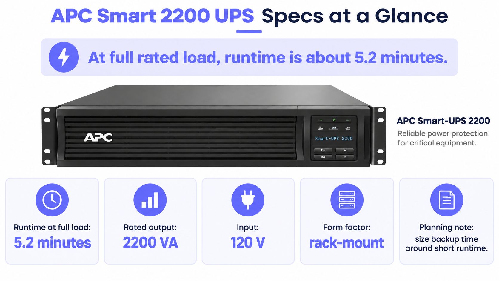
The Smart-UPS 2200 user manual documents the 2,200 VA, 1,980 W, 120 V rack-mount configuration, including its rack footprint, voltage windows, and communication interfaces. The specifications below apply to that configuration.
Smart-UPS 2200 specifications for the 120 V rack-mount model
| Specification | Smart-UPS 2200 (120 V rack-mount) | What it means in practice |
|---|---|---|
| Rated capacity | 2,200 VA | Apparent power, the headline figure on listings |
| Maximum output | 1,980 W | Real-power ceiling for everything connected |
| Power factor | About 0.90 | 1,980 W divided by 2,200 VA |
| Rack height | 2U | Standard rack-mount footprint |
| Nominal output | 120 V | Equipment and PDUs must match |
| Input voltage window | 82 to 144 V normal; 75 to 154 V adjustable | Regulation absorbs deep sags without draining the battery |
| Battery | Sealed lead-acid, RBC43 cartridge | Match the replacement cartridge to the exact unit |
| Recharge time | About 3 hours | A second outage during recharge draws on a partially charged battery |
Two rows drive every sizing decision. The 1,980 W ceiling is the denominator for load percentage: the closer measured demand runs to it, the shorter the shutdown window the battery can fund. The recharge time sets recovery between events, because an outage that ends with a drained battery leaves less than the published runtime available if power drops again the same afternoon.
The specification panel provides a quick visual reference for checking the intended installation.
Confirm electrical fit before ordering
This is a midrange infrastructure UPS sized for rack equipment: servers, storage, networking, point-of-sale systems, and telecommunications gear that need managed power protection.
The wide input window helps where utility voltage fluctuates. Connector type, circuit capacity, and grounding still need to match the unit's installation requirements.
Before purchase, complete these checks:
- Output compatibility: Confirm that the protected equipment accepts the UPS output voltage and outlet arrangement.
- Site supply: Match the actual input connection and circuit rating to the product label on the exact unit.
- Measured demand: Record total operating watts under real load, including storage, switches, and management equipment.
A compatible plug proves nothing on its own. All three checks need to pass before rack space becomes the deciding factor, because a unit that fits electrically but funds too short a shutdown window is still the wrong purchase.
Pros, Cons and Model Variants
The strongest reason to choose this platform is the combination of server-oriented power protection, automatic voltage regulation, and management options. It suits a compact infrastructure stack whose operator needs an orderly response to power loss.
The main limitation is operational rather than electrical. A rack can fit within the output rating while leaving too little time for application shutdown, storage flushing, and host power-off. Buying spare watt capacity doesn't automatically buy enough shutdown time.
Strengths and compromises
- Useful protection: Voltage regulation can handle routine supply variation without treating every disturbance as an outage.
- Manageable infrastructure: Direct-host connections and optional network management support different deployment sizes.
- Ongoing service: Batteries, firmware, alert routing, and shutdown software all require attention.
- Limited autonomy: Sustained operation requires a runtime strategy, not just a larger VA label.
Pricing also requires a part-number comparison rather than a family-name comparison.
| Separate model listing | Listed price | Listed maximum runtime at half load |
|---|---|---|
| Smart-UPS 2200VA LCD C rack model | €1,826.00 in the Bechtle rack-model listing for 2026 | 16 minutes at 50% load |
| Smart-UPS 2200VA LCD C 230V | €1,259.00 in the Bechtle LCD C listing for 2026 | 24 minutes at 50% load |
| Smart-UPS SMX 2200VA LCD 230V | €2,380.00 in the Bechtle SMX listing for 2026 | 25 minutes at 50% load |
These are separate models and voltage configurations, not interchangeable offers. Their runtime figures must stay attached to their respective products.
The APC Canada Smart-UPS X description also lists 2,200 VA and 1,980 W of maximum configurable power. Matching those headline ratings still doesn't establish identical runtime, batteries, outlets, or expansion support.
Procurement should compare exact part number, voltage, included management hardware, and battery configuration before comparing cost.
Runtime and Load Calculations for Real Racks
The 2,200 VA label reads like a backup promise. It works better as a shutdown-time budget: a fixed pool of minutes that has to cover everything from the first alert to the last host powering off. Sizing stops being "will it run the rack" and becomes "will it outlast the shutdown sequence."
Published runtime by load for the 120 V rack-mount model
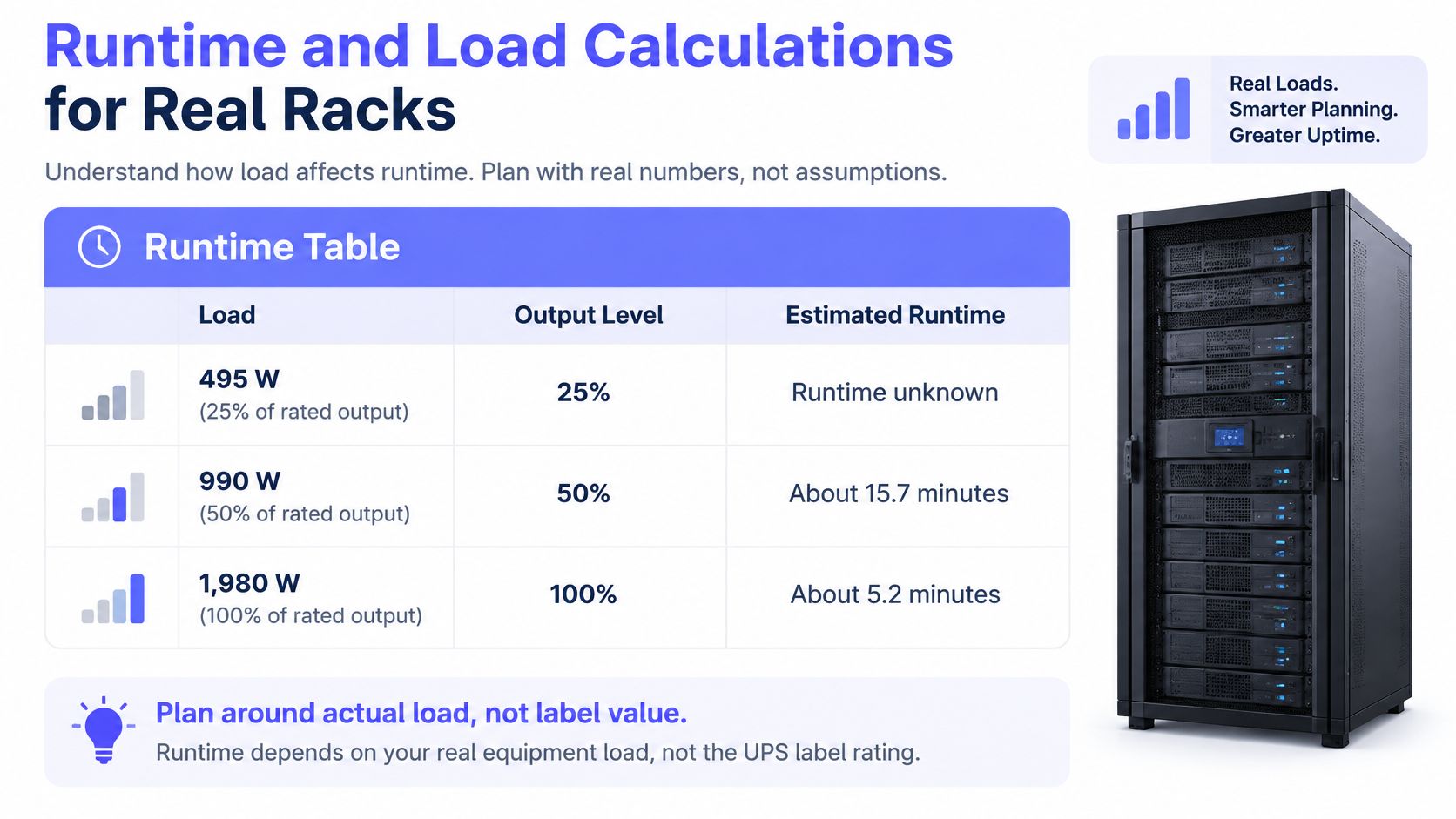
The rack-mount specification sheet provides the 990 W, approximately 15.7-minute and 1,980 W, approximately 5.2-minute test points below.
| Load | Share of 1,980 W rating | Published runtime |
|---|---|---|
| 495 W | 25% | Not published; exceeds the 50% load point |
| 990 W | 50% | About 15.7 minutes |
| 1,980 W | 100% | About 5.2 minutes |
These figures describe new, fully charged batteries under specified test conditions. Production batteries deliver less because of age, temperature, and the difference between a resistive test load and real switching power supplies. The gap between the two published points also shows the shape of the problem: doubling the load cuts runtime by roughly two thirds, not half.
Turn measured watts into a shutdown budget
Say a rack measures 1,500 W during a representative workload. Dividing that by the documented watt ceiling puts utilization near 76%, which looks comfortable on a capacity check. It says nothing about minutes. A load can sit well inside the nameplate rating and still leave only a short shutdown window, which is exactly why watt utilization alone is the wrong go/no-go test.
Runtime is not linear with load. Drawing a straight line between published test points works for preliminary screening, but it is an unsafe basis for a production shutdown timer. Use the exact model's runtime curve, then validate it against a controlled test.
A workable calculation follows this sequence:
- Measure the complete protected load. Use UPS telemetry or a metered PDU during normal operation and demanding workloads. Include the network and storage equipment required during shutdown.
- Time each shutdown operation. Record application stop, guest shutdown, host shutdown, storage flush, and any required network actions.
- Order tasks by dependency. Add sequential operations along the longest dependency path. Tasks that run in parallel don't all need to be added end to end.
- Compare elapsed shutdown time with usable runtime. Include command delays, monitoring intervals, retries, and the final power-off stage.
A virtualized host that finishes quickly during an idle test can take considerably longer while guests are writing heavily. The useful measurement is the shutdown sequence under representative conditions, not the fastest recorded result.
Planning rule: Runtime must cover the entire shutdown sequence with reserve remaining. Reaching battery exhaustion at the same moment as the last host powers off isn't a successful margin.
Preserve the dependencies
Storage should remain available until its clients have stopped writing. The management switch must remain powered while shutdown commands and acknowledgements still depend on it. Pull either one early and an orderly stop turns into a corruption event.
Physical rack changes can scramble those relationships. Teams reorganizing equipment can explore data center storage options for the physical layout while documenting separately where protected equipment, PDUs, and service access will sit. Cabinet order and cable paths change; the electrical dependency map has to be redrawn to match, because tidy racking does not reorder a shutdown.
That map is where the VA figure hides its risk. Nameplate capacity confirms the UPS can carry the load. It says nothing about whether the battery lasts longer than the longest dependency chain. For older or untested batteries, reduce the planning allowance rather than assuming catalogue performance. Where reserve is uncertain, start shutdown earlier and confirm the margin through testing.
Choosing Between USB, Serial, SNMP and Modbus
Connection methods compared for the Smart 2200
| Interface | Typical use | Strength | Limit |
|---|---|---|---|
| USB | Shutdown software on one host | Simple, no network setup | Direct connection serves one host; no fleet view by itself |
| DB-9 RS-232 | Legacy serial link to one host | Suitable for supported older host connections | One direct host and cable constraints |
| APC SmartSlot network card | Remote status and alerts over SNMP | Multi-host visibility and event traps | Needs IP setup and card configuration |
| Modbus | Building automation polling | Fits existing control systems | Support must be confirmed for the model and card firmware |
The correct interface depends on who must receive the power event and who must act on it. Monitoring and shutdown are related, but they aren't the same function.
Direct connection for a standalone host
USB is usually the cleanest option for a standalone server with supported shutdown software. Serial remains useful where an existing management host or established integration requires it.
Use the cable specified for the UPS connection. A connector that physically fits doesn't establish compatible wiring or protocol behavior.
The direct-connected host becomes part of the protection system. If its shutdown service is stopped, misconfigured, or unable to communicate, the UPS can continue supplying power while the server misses the instruction to shut down.
Network management for a shared rack
A compatible SmartSlot network card is the better fit when several hosts need UPS status or a remote operations team needs visibility. It adds configuration work and another managed network endpoint, but avoids treating a locally attached server as the only source of power information.
SNMP exposes status through objects defined in a management information base. The practical distinction between polling values and interpreting their definitions is explained in the SNMP and MIB guide.
A network card doesn't automatically coordinate shutdown across every host. Supported agents, orchestration, credentials, and dependency handling still need configuration.
An interface is selected successfully only when the intended shutdown action works, not merely when a dashboard displays battery status.
Modbus belongs in deployments where a building management system already uses it and the exact hardware supports it. A facilities polling system shouldn't become the only source of server shutdown commands unless that integration has been designed and tested.
Choose the management path before mounting the UPS. Cable routing, card access, host software, and the installation procedure all depend on that decision.
How to Install the Smart 2200 in a Rack or Tower
Installation should begin with the exact model's manual, not assumptions carried over from another Smart-UPS. Input connections, battery handling, mounting hardware, and permitted orientation can differ.
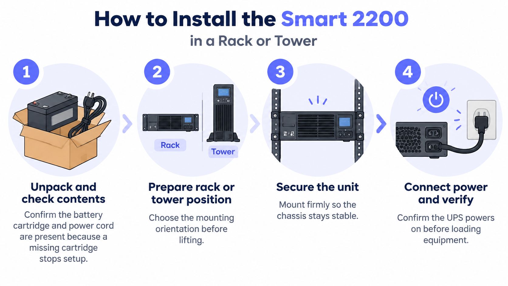
The installation overview provides the physical sequence; electrical work must follow the unit label and site requirements.
Rack installation procedure
Check the delivered contents. Compare the chassis, battery cartridge, power connection, rails, and accessories with the packing list. Inspect for shipping damage before energizing the equipment.
Prepare the rack position. Confirm sufficient mounting space, rail compatibility, rack stability, and access for battery service. Keep the actual chassis ventilation paths clear rather than assuming every model uses identical airflow.
Fit the rails and secure the chassis. Follow the rail instructions and site lifting procedure. Use assisted lifting or lifting equipment as appropriate, support the chassis from its base, and don't use the front handles as lifting points.
Connect the battery correctly. Seat the cartridge and fully engage the battery connector according to the manual. An incompletely connected battery is a common commissioning mistake: utility-powered operation can look normal until testing exposes the fault.
Connect the specified supply. Use a properly grounded circuit sized for the UPS input requirements, including charging demand. A common mistake is choosing a convenient shared receptacle without checking its existing load and protection.
Attach the protected equipment. Map every load to its intended outlet or controlled outlet group. Use surge-only outlets for noncritical equipment only if the exact model provides them.
Connect the chosen management interface. Install the USB, supported serial, or network connection and secure cables without blocking service access. Label both ends so troubleshooting doesn't require tracing an unidentified cable through the rack.
Commission the UPS. Apply power, allow the required charging period, run the supported self-test, and inspect active alarms. Confirm the measured load is sensible before enabling production shutdown automation.
Record the baseline. Log installation date, battery date, serial number, firmware, circuit identification, and initial test result. Save the outlet map with the shutdown procedure.
Tower placement and site changes
For a tower model, use the manufacturer-approved orientation and supports on a stable, ventilated surface. A rack chassis shouldn't be stood on its side unless its instructions explicitly permit that arrangement.
A larger deployment may require site-level planning before the UPS is installed. Teams assessing a new equipment location can evaluate prefabricated data center options from Pacific Mobile Structures, Inc., alongside electrical supply, cooling, and service-access requirements.
Finish commissioning with the rack in its normal operating state. An unloaded self-test doesn't validate the completed installation, its monitoring path, or the host shutdown sequence.
How to Configure SNMP Alerts and Send Telemetry
SNMP configuration should produce actionable telemetry without exposing management controls. Confirm the card's supported protocol versions, authentication options, and object mappings before configuring the monitoring platform.
The monitoring workflow needs both UPS visibility and a separate, verified shutdown mechanism.
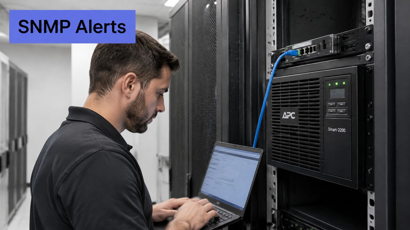
Configure collection and escalation
Assign a stable management address. Use the site's approved static-address or reservation process. Restrict access to the systems that need to poll or administer the card.
Use authenticated, encrypted SNMP where supported. Create a read-only monitoring identity. If the card only supports an older community-based implementation, isolate it on the management network and plan its security limitations explicitly.
Configure polling and traps separately. Point the trap destination at the intended receiver and permit only the necessary management traffic. Successful polling doesn't prove that unsolicited event notifications can reach the receiver.
Load the appropriate MIB definitions. Start with the standard UPS objects the card supports, then use the vendor MIB for additional fields. Verify units, scaling, and unsupported values rather than assuming every object is implemented.
Register and validate the device. Compare reported battery state, remaining runtime, input voltage, and output load with the card interface. The network-device monitoring guide provides context for integrating network telemetry. Adding uptime checks and SNMP network devices in Fivenines each takes another minute or two; validating their meaning still requires engineering attention.
Set thresholds from operating requirements. Alert on transition to battery, insufficient remaining runtime, abnormal temperature, and sustained load approaching the operating ceiling. The runtime threshold should exceed the complete shutdown budget, including reserve.
Route alerts to an attended channel. Assign ownership and escalation outside office hours. A notification sent to an unattended mailbox isn't an operational response.
A video walkthrough can supplement the configuration work, but the installed card's documentation remains authoritative for supported features.
Prove the complete event chain
Test safely under controlled conditions. Begin with supported self-tests, then validate mains-loss behavior on non-production equipment using an approved upstream isolation method that preserves protective grounding. Don't casually unplug a live UPS to simulate an outage.
Record thresholds and outcomes. Save the event time, notification delivery, shutdown trigger, host completion, and remaining reserve. Document why each threshold exists so later changes don't remove the safety margin.
Expected on-battery notification should precede the planned shutdown action. Emergency low-runtime handling must still operate independently if an earlier notification is lost.
Read-only monitoring credentials shouldn't be repurposed for power-control actions. Any automation capable of shutting down outlets or hosts needs separately controlled access and an explicit recovery procedure.
Battery Life, Firmware and Routine Maintenance
Battery age doesn't establish battery capability. The Smart-UPS maintenance documentation illustrates conflicting expectations across variants: some documentation gives five to ten years, while other Smart-UPS manuals state two to five years.
The same documentation identifies high temperature, poor utility power, and frequent short discharges as factors that shorten service life. Replacement planning should therefore use the actual operating environment and measured runtime, not a calendar alone.
A passed self-test isn't a runtime guarantee
A self-test can identify faults without proving that the battery will support the entire shutdown sequence. A battery may pass a short diagnostic and still deliver inadequate runtime under the production load.
Waiting for the replacement indicator is reactive. Operators need evidence that the battery can still support the required operating window before the next outage.
Service criterion: A battery is operationally adequate only while its usable runtime exceeds the shutdown requirement with reserve.
Recharge state also needs care. Some models recover much of their capacity before reaching full runtime capability, so a reassuring display after an outage shouldn't automatically authorize another demanding test.
Establish a maintenance rhythm
Use a recurring calendar, adjusted to the model's instructions and the site's risk:
- Monthly review: Inspect runtime trends, input events, battery transfers, and active alarms. Run the supported self-test at an appropriate interval.
- Planned discharge validation: Schedule controlled testing during maintenance windows, with closer scrutiny for older batteries or declining runtime.
- Environmental inspection: Clear obstructed vents, check ambient conditions, and investigate unusual heat.
- Firmware review: Evaluate UPS and network-card updates with other infrastructure changes, including compatibility and rollback requirements.
Avoid repeated deep-discharge tests merely to produce a fresh runtime number. Testing itself consumes battery life, so the procedure should answer a specific operational question.
After replacement, record the cartridge identity and date, complete the prescribed charging and test process, and reset battery records where required. Reworx Recycling's guidance on compliant battery disposal for IT teams helps teams plan collection and documentation instead of leaving spent cartridges in equipment rooms.
Record UPS and network-card firmware versions before and after changes. Keep those records alongside battery history so a changed runtime estimate or communication fault can be investigated against an actual maintenance timeline.
Common Faults and How to Fix Them
Frequent transfers to battery should trigger an input-supply investigation before a battery order. UPS logs can help distinguish voltage disturbances from communication faults or failing battery performance.
Smart 2200 symptoms, likely causes and fixes
| Symptom | Likely cause | Fix |
|---|---|---|
| Frequent switches to battery | Input outside the configured voltage window or an unstable feed | Review logged input voltage, then inspect the upstream circuit and generator-transfer behavior |
| Runtime far below the published figure | Aged battery, higher actual demand, or an unsuitable load profile | Compare the load log with a controlled discharge test; replace the battery if it cannot meet the requirement |
| Battery replacement alarm | End-of-life battery, failed cell, or connection fault | Check the connection and fit the matching cartridge, RBC43 only where specified for the exact unit |
| Slow or incomplete recharge | Degraded battery, high temperature, or insufficient recovery time | Check ventilation and temperature, allow the model's specified charging period, then retest |
| Overload indicator active | Connected load exceeds available output capacity | Check measured load and startup behavior; remove noncritical equipment or add suitable capacity |
| No SNMP data | Incorrect card address, credentials, access rules, or blocked management traffic | Verify card reachability, protocol settings, monitoring identity, and permitted polling traffic |
| No automatic shutdown during a test | Communication failure or shutdown software not configured | Check service status, event policy, cable, and device mapping; correct the fault and repeat the controlled test |
Separate the fault from the symptom
Short runtime doesn't prove that the battery is defective. A changed workload, newly added storage shelf, or unexpected startup demand can invalidate an earlier test.
Likewise, an overload alarm isn't exclusively a steady-state watt problem. Check the UPS event details, apparent-power loading, and startup behavior before deciding that a smaller battery-backed load is the only remedy.
For missing telemetry, start with a narrow query against a supported object. The snmpwalk and OID troubleshooting guide helps distinguish transport or credential failures from a monitoring template that requests unsupported objects.
Retest the function that failed
A repaired cable should be followed by a communication test and a shutdown-policy test. A replacement battery should be followed by the prescribed commissioning process, not merely dismissal of the alarm.
Keep power-protection tests separate from production incident response wherever possible. Deliberately creating another interruption while investigating an unstable UPS can turn a manageable fault into an outage.
Escalate to APC support or a qualified service partner when a correctly specified replacement battery fails commissioning, or when faults recur on a recently installed unit. Internal electrical faults aren't a reason to open the chassis outside authorized service procedures.
Confirm Your Shutdown Plan Before the Next Outage
A rack is ready only when the operating record contains the following evidence:
- Measured demand: Actual watts for each protected host and supporting device, including representative workload peaks.
- Dependency timing: Graceful shutdown duration for applications, guests, hosts, storage, and network dependencies.
- Available reserve: Tested or conservatively established runtime at the measured load, exceeding the complete shutdown budget.
- Working response: Verified event detection, alert delivery, escalation, and shutdown execution.
- Battery evidence: Recorded battery identity, test date, and usable-runtime result.
The decision rule is straightforward: if shutdown requires more time than the battery can safely provide, the deployment isn't ready. Reduce protected demand, add appropriately designed UPS capacity, or separate noncritical equipment before the next outage.
Moving a device to another outlet on the same UPS doesn't add energy. Moving it to utility power also means accepting that it may disappear immediately during a power failure, so its dependencies must be checked first.
Keep shutdown and recovery requirements distinct
Orderly shutdown protects data and equipment, but it doesn't establish how quickly service can return. The recovery time objective guide provides the separate framework for deciding how long restoration may take.
Recovery planning should identify startup order, storage availability, application checks, and who authorizes a return to service. Automatic restart without those conditions can leave hosts running while essential dependencies remain unavailable.
For fleets, Fivenines combines server metrics, SNMP network monitoring, uptime checks, and cron jobs in one tool. Each server, uptime check, cron task, SNMP device, and MQTT topic monitor counts toward a plan's monitor limit; client capacity therefore depends on the infrastructure being monitored.
A shared dashboard helps operators correlate a site power event with UPS state and host availability. It doesn't replace local shutdown execution or the documented dependency sequence.
Run the measured-load calculation for the most critical rack this week, then write down the shutdown budget and the evidence supporting its reserve.
Fivenines brings server metrics, SNMP network monitoring, uptime checks, and cron jobs into one tool so operators can connect UPS events with infrastructure health. Visit Fivenines to bring power telemetry and host visibility together, then validate the shutdown plan against the actual rack load.